About
Hello,
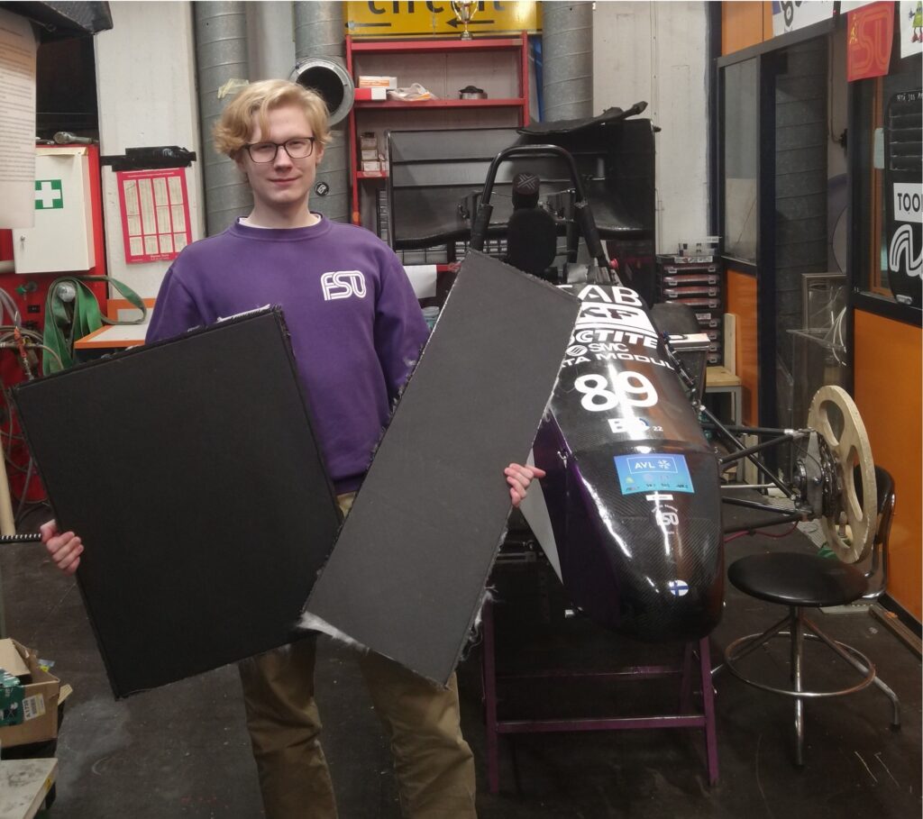
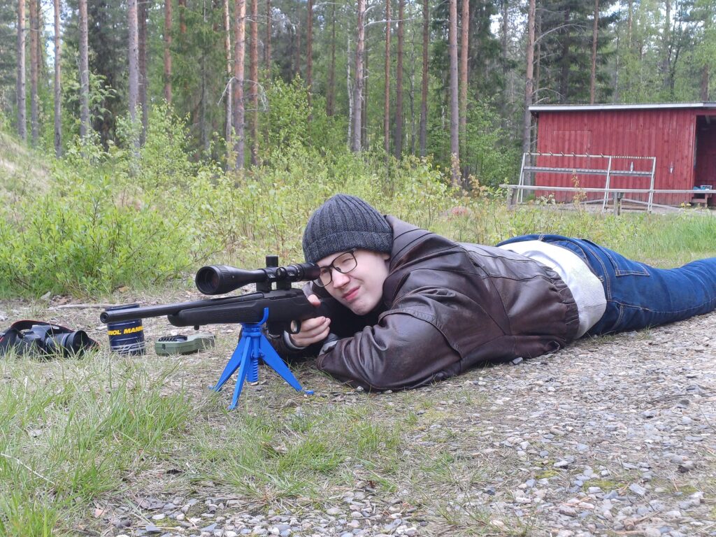
My name is Tuukka Junttila. I’m a mechanical engineering student from Northern Finland.
I’m the sort of person who spends all of their spare time on different sorts of engineering projects. Whether it be Formula Student or personal ones.
Some of those personal projects have matured enough to to showcase them publicly or even sell so I made this website!
Projects
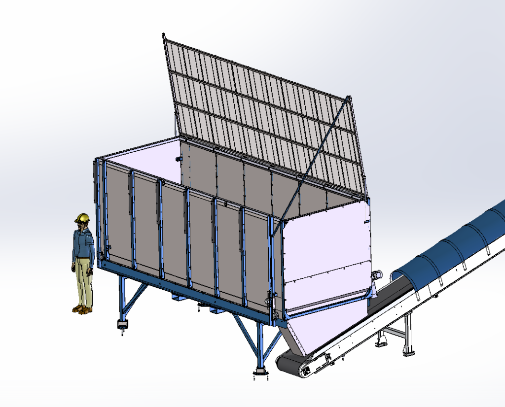
10m^3 Scaleable General Purpose Feed Bunker
This is a project I made for an industrial equipment company as a summer intern.
Here are some main points to describe the design
- A proficient welder will charge more than 100€/h while bolts, nuts and rivets can be had for 10€/kg so the number of welded joints was minimized.
- Said welder will take a longer time/charge more if the welds are difficult, so what welded parts there are were made small enough to fit on a welding table and all welded assemblies were made to be first bolted together before welding so no separate jigs are necessary.
- Making threads is a pain so where threads are required through holes and nuts or rivet nuts were always used.
- Instead of normal nuts, nylock nuts were used almost everywhere to guard against loosening.
- Laser cutting is cheap and yields accurate parts, almost all parts are made out of either sheet steel on a laser cutter or with a profile laser cutter
- Milling is expensive. There is not a single machined part in the whole machine other than two key slots made on axles.
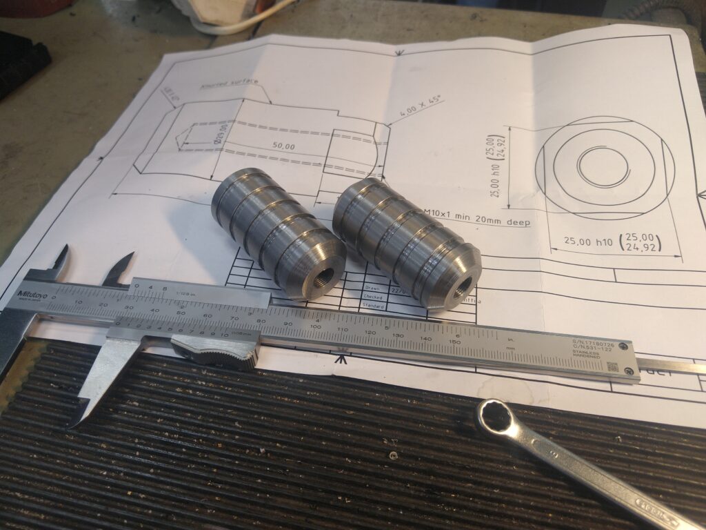
- Turning is expensive. The only turned parts are motor fits on two axles whose blanks are already the correct size for the pillow blocks used.
- Having to hand fit parts together takes time and is a pain so all holes were oversized as much as possible and accurately positioned by laser cutter to make sure that everything fits.
- By removing the feet everything fits in a standard shipping container
- The whole machine can be pre fabricated, flat packed in a small space, and assembled using common hand tools
CNC Milling Machine
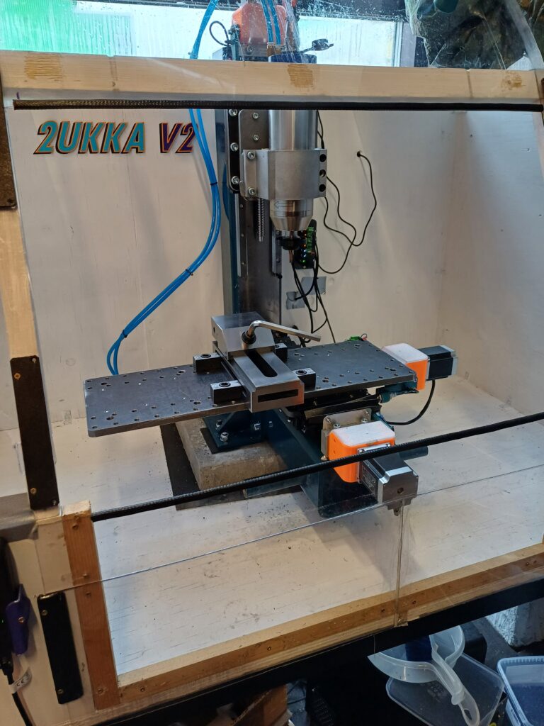
Me and my friend wanted the capability to CNC machine metal ourselves and off the shelf machines seemed either very expensive or just disappointing so instead we sank hundreds of manhours into building our own CNC machine.
It has a square SHS steel frame filled with concrete, normal Nema 57 steppers, 16mm ball screws, 20 mm HRC linear rails, a 2.2 kW spindle, it weighs 120kg.
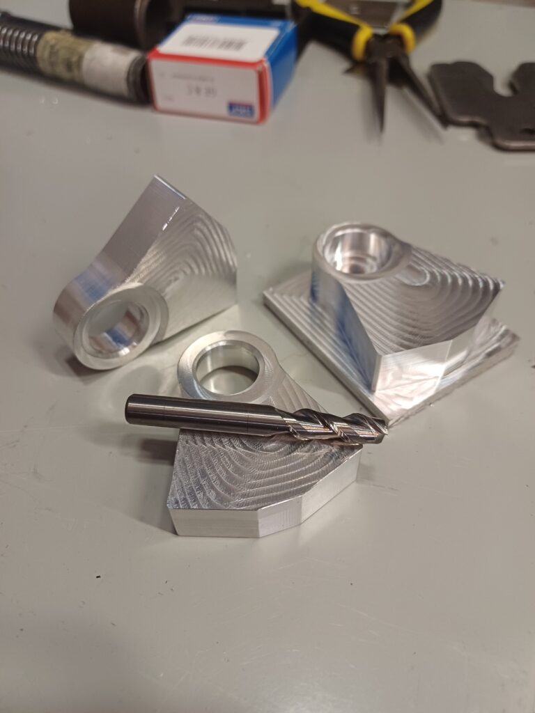
It machines aluminum quite well at approx 30 cm^3/min MRR with an 8mm 3 flute cutter at 16mm DOC.
It can also cut steel passingly.
Formula Student Steering Gearbox
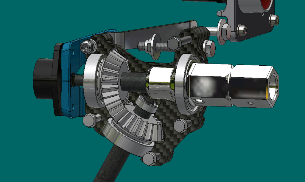
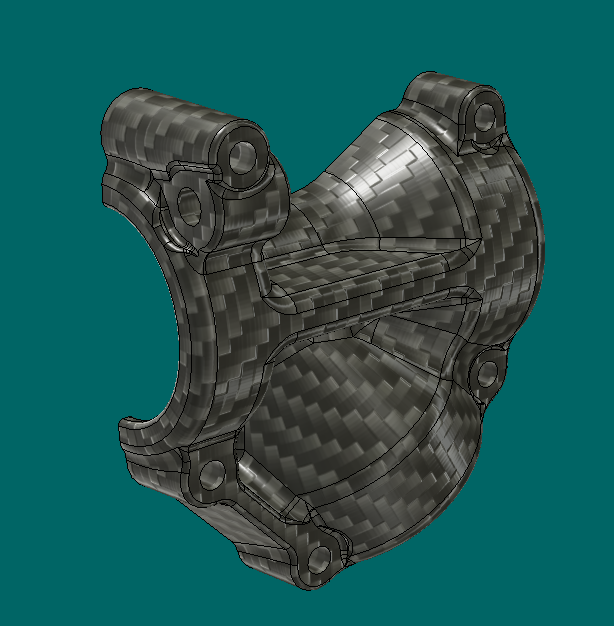
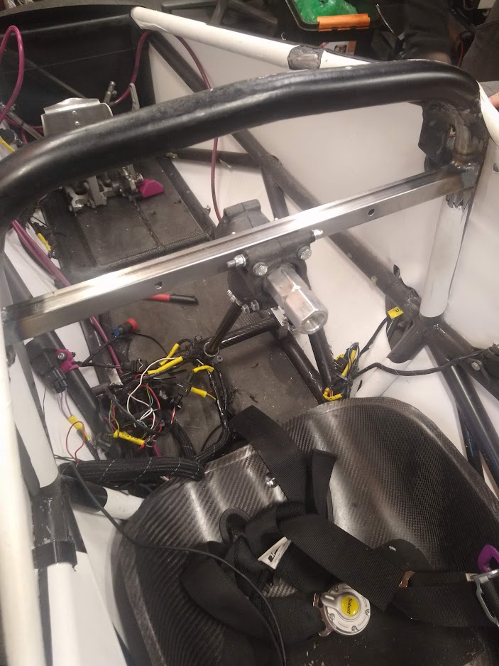
This design is a replacement for the more common 90° steering gearbox you can find in many Formula Student cars. The idea was to reduce the length of shaft required by routing it more straightly towards the steering rack and therefore to save weight.
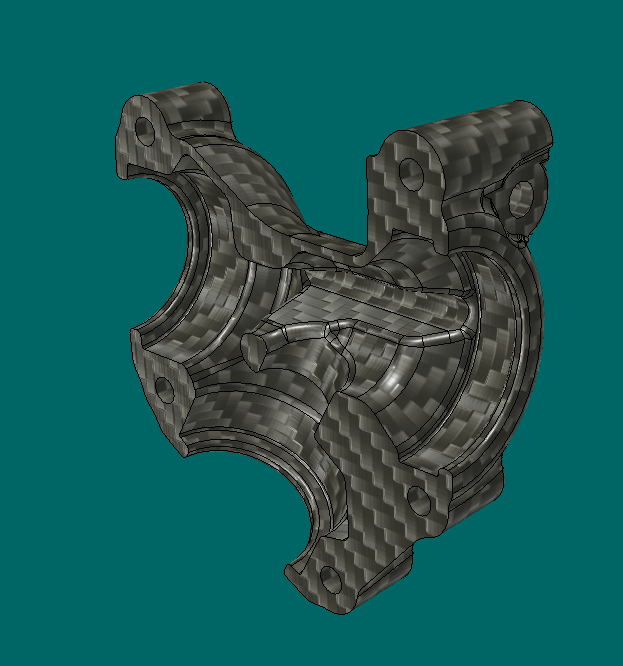
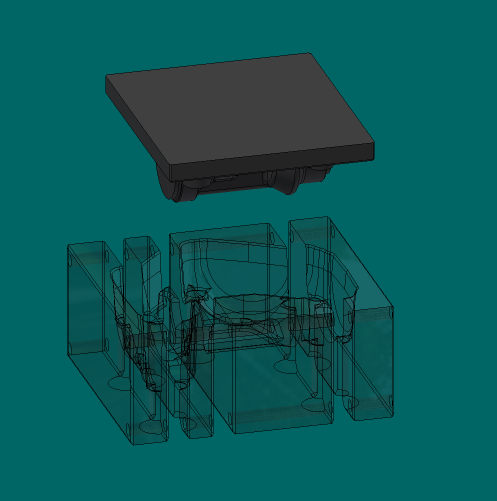
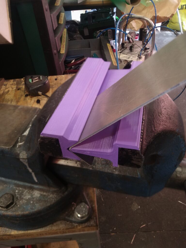
A molded carbon fiber shell with 3D printed molds was used for this project. The inspiration for using “forged carbon fiber” this way was Easy Composites Youtube guides and the method worked quite well!
Carbon Fiber Suspension Arm Manufacturing Method
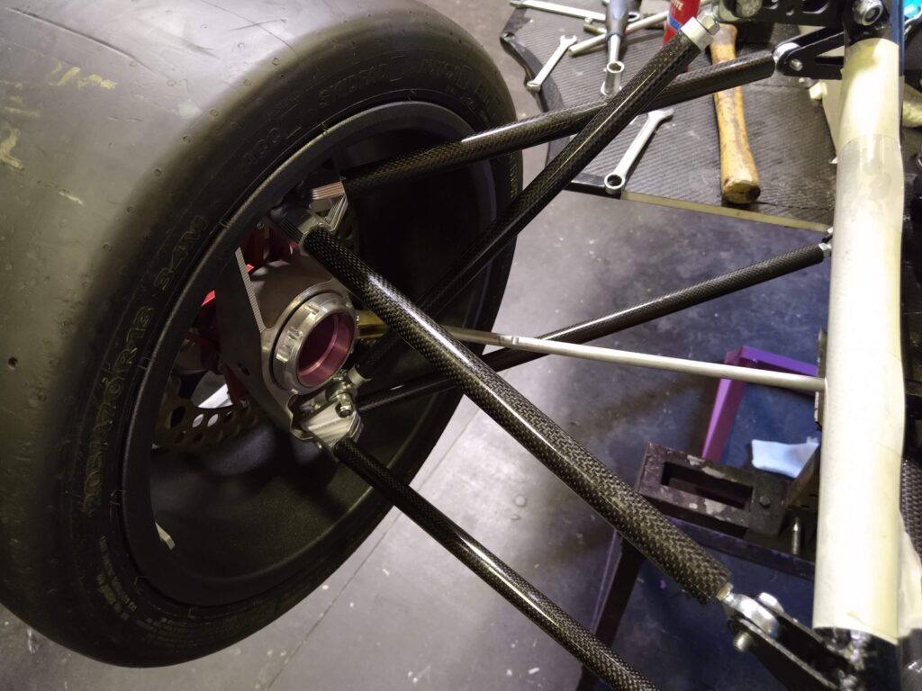
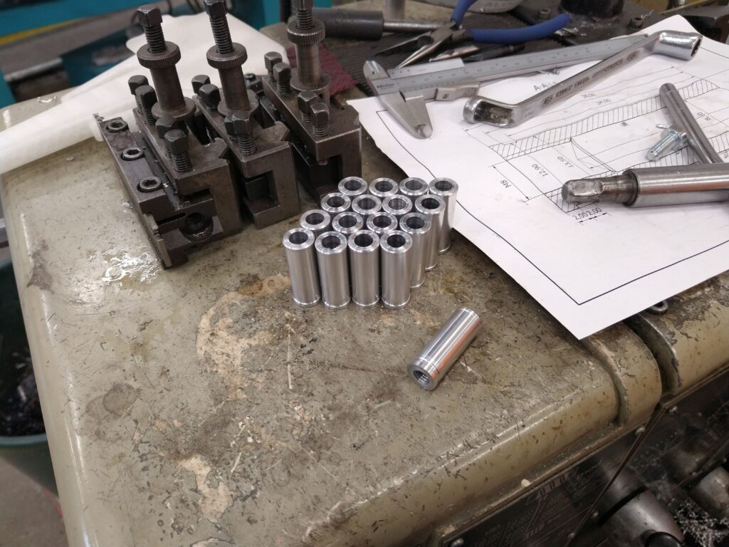
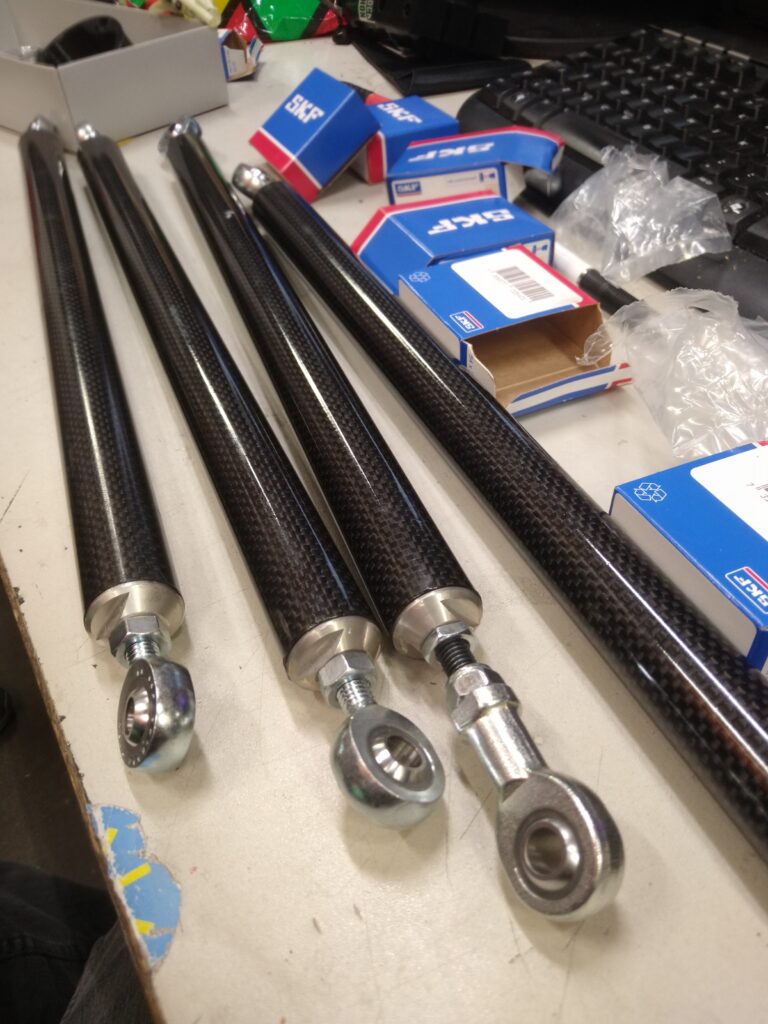
My Formula Student team had hoped to make CFRP suspension rods for some time so I took on the project. I had to consider some of the following aspects
- Repeatability of the process
- Making sure that you can observe the success or failure of the joint during manufacture
- Easy to learn steps
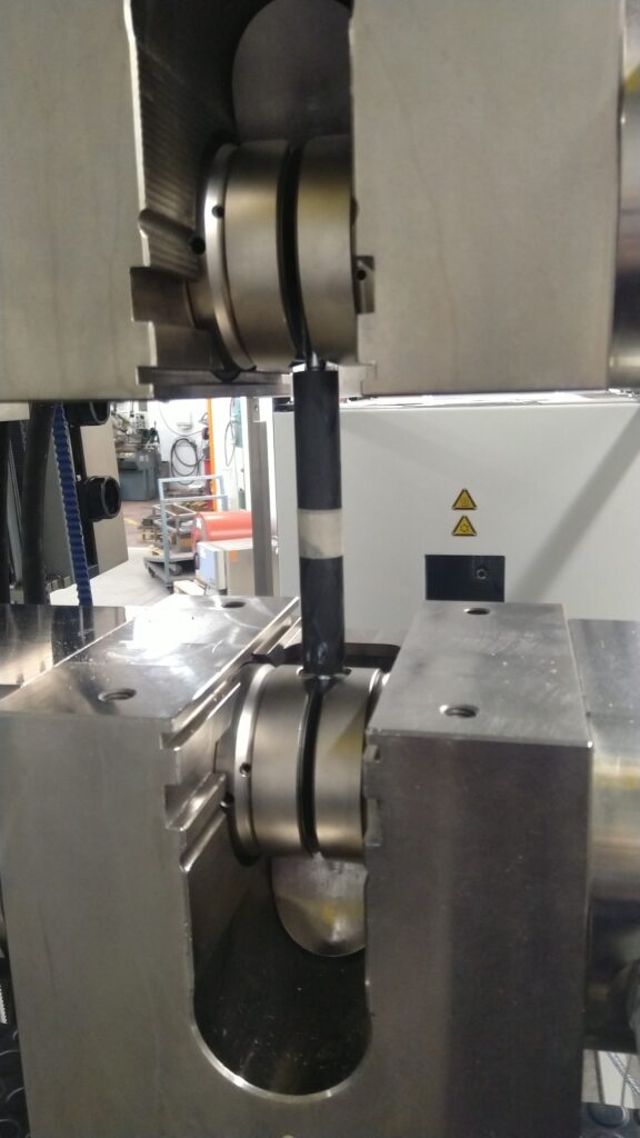
- How to estimate glue joint strength for long term fatigue scenario
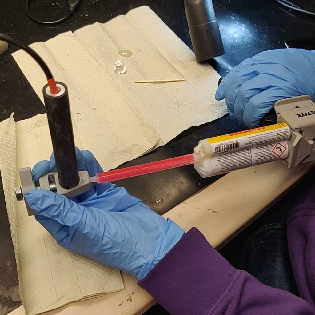
- High performance glue joint with available tools and processes
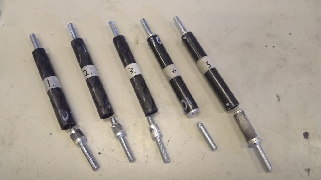
I found that the most important aspects in the process were the surface prep of the carbon fiber tubes and the aluminum inserts, the complete spread of the glue inside the joint, and most importantly repeatability of the whole process as it is difficult to inspect if a joint is succesful and can handle 30 kN or if it is a failure and will fail at 5 kN.
After a lot of testing I arrived at a process that works and my team has used it for many years so far without failure.
Brake disks for a Formula Student car
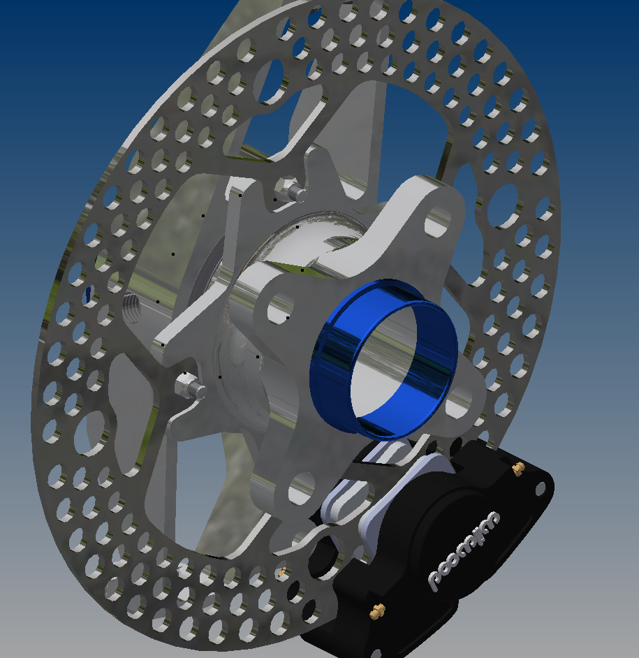
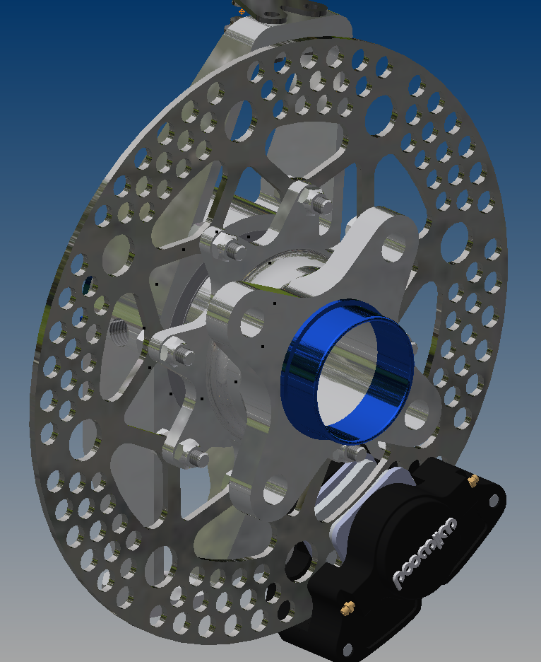
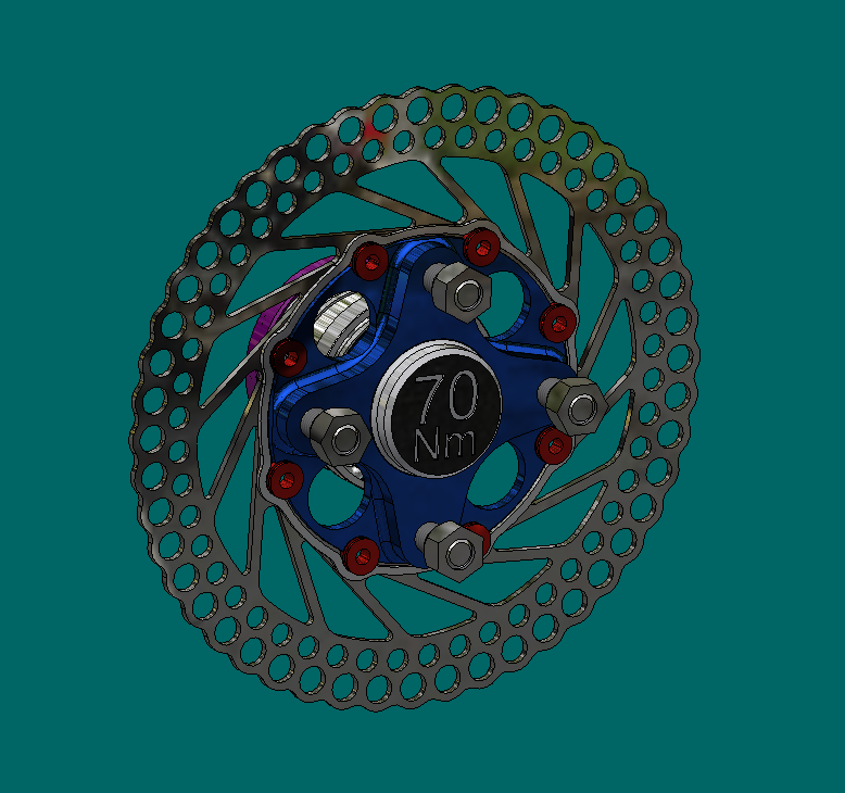
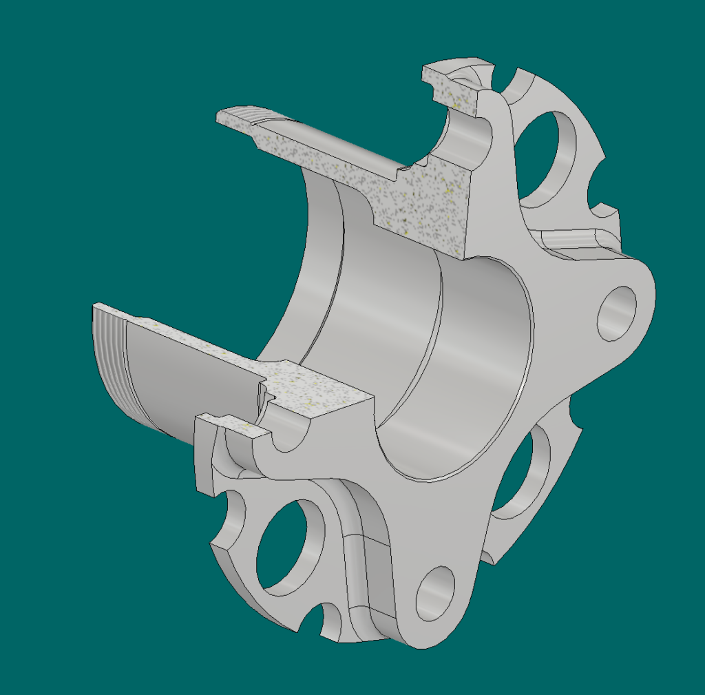
Brake disks need to be strongly connected to the wheel hub and yet there should be a bit of play to account for the disk not being perfectly straight etc.
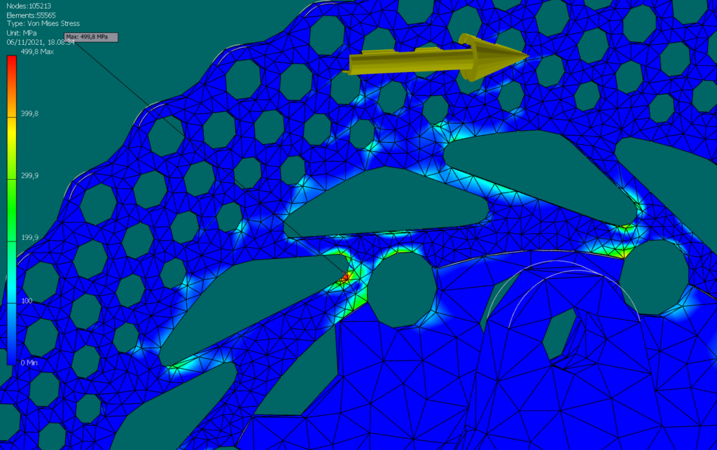
During this design process I explored many different brake disk designs until I finally ended up using a fairly standard solution, motorcycle floated buttons. They are an easy and reliable off the shelf solution for the problem. I also optimized the brake disk shape for strength and weight, the ribs connecting the disk part to the floater ring were made as light as possible to save weight whereas some weight was left on the outer disk as a heatsink.
In the end these disks weigh only 340g which is less than any other front brake disk on a Formula Student car I’ve seen so far. Many teams are using very heavy disks for no reason as far as I know.
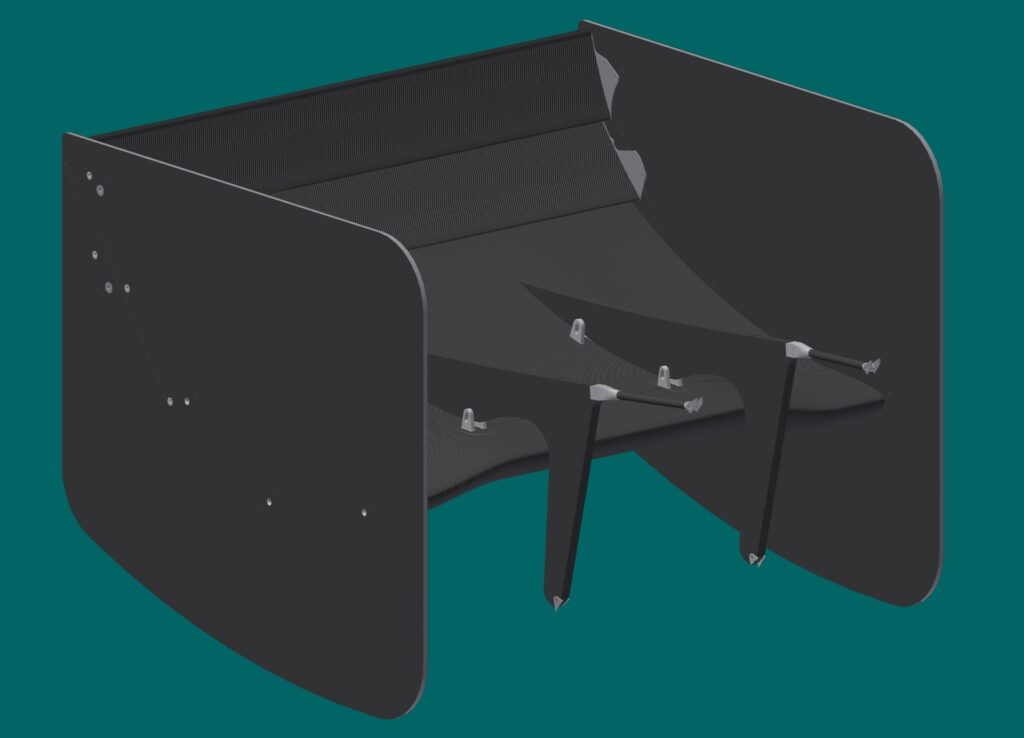
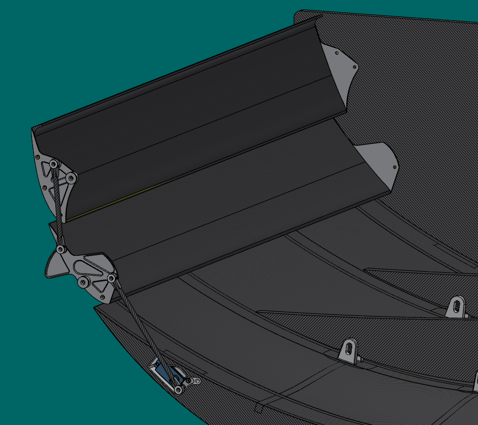
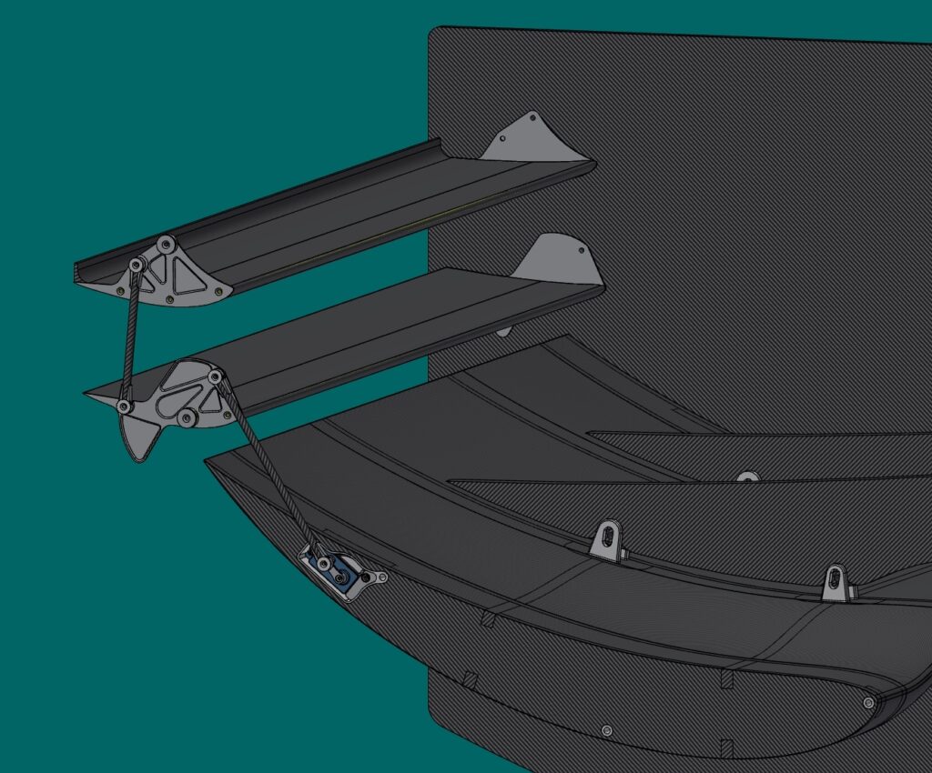
Formula Student Car Rear Wing DRS Mechanism
The point of a drag reduction system (DRS) in race cars is to reduce the air friction to help speed up on straights while allowing to benefit from the downforce of the rear wing in corners.
The system I designed used two servos nested inside the 1st element of the rear wing connected to the other elements which have bearings situated in their center of pressure. The system was completely enclosed inside the endplates, lightweight, quite fast and functional.
However in Formula Student the straights are very short and there are a lot of corners. During actual track driving this system ended up remaining almost always shut. It was removed in the next year’s car even though the mechanics did work well.
